gamebox
Member

Offline
View
Posts
View Gallery
|
Hello all.  I'm a new member of the forum, although I actively follow you via FB and by jumping into user galleries here from time to time for years. I have a question about unusual behavior of Bodi, Chinese made 15W 220V 2U 2700K (probably halophosphate) CFL, just like the one on the picture (found on the internet). 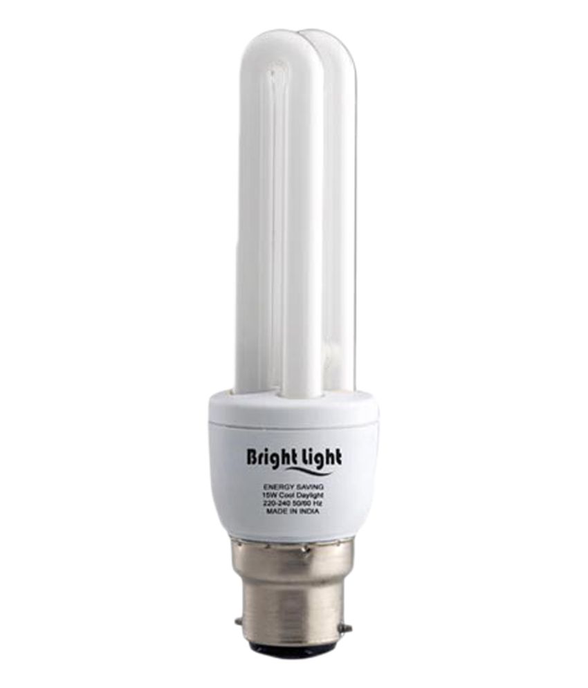 I got this CFL with fried electronics but the tube seemed like new. Opened it and verified that both filaments are indeed conducting @ about 14-15 ohm, and that the tube is not cracked. Now, while testing it, it first fried me some random 14W CFL's electronics (it turns out a pair of filament lead wires was not isolated well so they shorted in the tube's base). When tested on another dead CFL's electronics, it lit up just at the ends (it did so on the first one as well, of course that time with only one filament lit) but would not "strike" (light up in full-length). Then I used a magnetic ballast for small 2U (3U?) fluorescent tubes (I think that type of bulb is called "PLC"), which says it is suitable for 7-9-11 W, connected it to the tube and Philips S10 starter, but the behavior remained pretty much the same - glow at the ends, with starter closing and opening, but still no strike. The glow is in regular "phosphor" color of the tube (2700K), so there is probably some mercury inside to emit UV. I need your opinion here - is this a mercury starved tube, argon starved, has some issue with the emitter on the filaments, or what? Any way to further test it, anything to do to it to try "fixing" it? After first unsuccessful test (with one filament shorted) some sputtering occurred on the inside of the other end (around the filament that got overloaded for a short while), but that seems negligible and the darkening is still almost completely invisible from the outside (it lasted just 2 or 3 seconds before transistors were killed). I'm still curious whether this one can be lit. Thanks in advance for any opinions. |
|
|
|
 Logged
|
|
nicksfans
Member

Offline
Gender: 
View
Posts
View Gallery

Down with lamp bans!
   
|
| It's possible that none of the ballasts you tried had a high enough OCV to strike this particular lamp. I would try an electronic instant start ballast (600+ OCV) or something similar, but those might be harder to find where you live (somewhere in 220V territory I assume) than in North America where they are very common. If you have access to a neon transformer, that would work too.
|
|
|
|
Logged
|
I like my lamps thick, my ballasts heavy, and my fixtures tough.
My Gallery
Instagram
YouTube
|
Solanaceae
Member
Offline
Gender:
View
Posts
View Gallery

All photos are brought to you by Bubby industries.
|
| Maybe it is just the tube. China is known for varying quality of manufacturing. One cfl can greatly outlive all of the batch or it could be the first to go by a long shot. You never know, especially with off brand CFLs like utilitech or great value.
|
|
|
|
Logged
|
Me💡Irl
My LG Gallery
My GoL Gallery
|
Medved
Member
Offline
Gender:
View
Posts
View Gallery
|
| The emitter on the electrodes is just spent, or there is some gas poisoning preventing te ignition, so the tube is at the end of it's life. That is, why the starter was not able to ignite it.
This state tend to overload the electronic ballasts. The reason is, these ballasts use resonance to generate high voltage for the ignition, which is associated with rather high currents and hard switching of the transistors, both cause quite high power dissipation in there. Normally this takes less than a second after power ON, till the lamp reaches normal, hot cathode arc state, when the power dissipation in the transistors is very small (usually less than 100mW; that's why even TO92 package is sufficient). During such short time, just the thermal inertia of the transistors is sufficient to prevent their temperature to exceed safe limit, so the whole system works well.
When the lamp does not want to ignite, or the electrodes operate just in a cold cathode mode (so with about 150..200V extra voltage drop), the high current resonance state persist till either a filament blows (and in that way interrupts the oscillator feedback, so stop the ballast), or the transistors overheat and fail.
As in any case it normally means the whole assembly gets trashed, so there is usually no attempt to save the ballast after the lamp fails, just a fuse to disconnect it from the mains.
With "big fluorescent" ballasts, either a separate circuit is employed making sure the high current state is limited in time (usually by detecting failed lamp and shutting down the ballast), or the used transistors are the ones capable to handle the elevated current (in an attempt to ensure the filament blows first; mainly with the simple, cheepeese ballasts).
Shorting one of the filament by itself does not overload the other, nor the ballast at all, in any case the filaments are fed by essentially a constant current source, so the current stays the same regardless of the total resistance (it is the ballast, what dictates the current).
By the way when trying to start the lamp on a "magnetic" ballast, I always start by manual preheating. At first I do not have to look for the suitable starter and second, it uses to be more reliable starting method (so if the lamp does not start manually, it definitely won't by the starter).
|
|
|
|
Logged
|
No more selfballasted c***
|
gamebox
Member
Offline
View
Posts
View Gallery
|
Thanks a lot, guys. @Medved: I'm not sure what the exact (typical) behavior of electronic ballasts with a bad tube present is. When my GE 20W "Decor" WW spiral CFL died some years ago (the filament depleted the emission mix first, then burned out some time later), I tried to relight the tube once again on the same ballast by shorting the open filament. It actually lit up, stayed on with (at moments) unstable light intensity, but after about a minute the other filament also opened because of (it seemed so) thermal overload, as it glowed stronger than normal. Btw, the ballast had PTC to switch off the filaments' current after ignition. I did the same experiment with a spent Philips Genie 8W WW CLF as well, that time with a low-resistance big-dissipation resistor connected in parallel to the dead filament, but that one also died fairly quickly after lighting up (the transistors blew into pieces, that ballast had no PTC in filaments' circuit). It might be that the emission mix on the filaments of Bodi 15W one is not ok, they did change their "light" intensity slightly while the tube was being preheated, and for short periods of time turned slightly reddish as well. Nevermind, I got it for free to play with, I just thought it was one of the regular ballast quality issues I am very used to seeing in these, and that it could be fixed. Now, I have another question (unrelated). Is it safe to test 10W T8 linear tube on a 18-20W T8 simple (low-cost chinese) electronic ballast? Will it overload the tube, run it at unsafe current levels? I don't have the appropriate one to test this tube... Also, can the opposite be done - put an 18W T8 tube on an electronic ballast meant for 10-15W T8 - I have the one that needs to be tested, but don't have it's original tube (nor I know it's rated power as it is from a disassembled fixture)? Thanks again. |
|
|
|
Logged
|
|
Medved
Member
Offline
Gender:
View
Posts
View Gallery
|
| The basic circuit has the filament usually connected in series with the rsonant LC, the arc becomes effectively parallel to the capacitor.
When the tube is not lit, high current flows through the circuit (so heats up the filaments quite quickly) and at the same time HV is present across the capacitor (normally that ignites the discharge). Once the discharge ignites, the arc forms rather low resistance, so reduces the quality factor of the LC way below unity, so the resonance disappear. With that the voltage drops down to the normal arc voltage, most of the current flows through the arc and only very limited current remains "for the heater" (it means just few percent of the total heating the filament gets from the discharge itself, so practically speaking it is zero).
Most frequently with that base circuit the discharge strkes before the filaments are fully warmed up. In that case the discharge efective resistance is still rather high, so the ballast is able to feed the extra voltage drop caused by the cold cathodes. This means two things: The extra voltage drop means quite significant power dissipation bythe ion bombardment (by the way the same bombardment responsible for the sputtering), plus as the voltage is still rather high, quite significant currents flows through the capacitor, so the filaments get a lot of heat just from Joule heating of the passing capacitor current. The combination of these means the filaments get warmed up (so transition the lamp to the low voltage drop hot cathode mode) very quickly, so to big extend reduce the sputtering.
The PTC is just connected parallel to the resonant capacitor. It's function is to short out the arc when it still cold, so just the filaments get heating power without the voltage, so the filaments get preheated. After the PTC warms up, the resonance effect take place, so the voltage goes up and usually immediately ignites the arc (with cathodes already hot). After startup, the circuit becomes essentially the same as the type without the PTC, so e.g. still some small current is flowing through the filaments.
Now if the emission mix wears off, the lamp either does not ignite, or stays just in the "cold cathode" mode. There the voltage across the capacitor remains high, so the high current remains in the circuit and continues to heat thefilaments. Original design idea was this elevated current overheats one ofthe filaments, so in that way breaks the LC circuit (and with most CFL designs that means interruption of the oscillator feedback). With modern transistors te normal power dissipation is so low, the tiny TO92 are sufficient. But these have so little margin, then they tend to fail before the filament blows in the case of faulty lamp, but still in many cases (mainly with higher power lamps) the filament is, what breaks first and so in that way protect the electronic, actink like a fuse.
But once you bypass one of the filaments, you essentially bypass the fuse, so the ballast starts to operate again, usually till the other "fuse" (=filament) blows. If you bypass even that, then there is nothing remaining, but the transistors overheating.
With the operation without the emission coat the drop tends to lower, when the tungsten heats up to really high temperature. But still it needs rather high cathode drop for that and that means less stable arc, so the flickering. Plus the real power drawn from the DC supply (coming from the bridge rectifier and filter electrolytic capacitor), the capacitor becomes insufficient to handle that, so sometimes it is that component, which fails as first.
|
|
|
|
Logged
|
No more selfballasted c***
|
Medved
Member
Offline
Gender:
View
Posts
View Gallery
|
| Now for the "10W T8":
There are actually two types in use in Europe. One is ~30cm long, other about 50cm (longer than F15T8).
The first one is rated for ~0.22A, so works on the same ballast as F15T8.
The longer is rated for 0.17A, so uses the same ballast as 7..11W PL-S or 6..13W T5 lamps.
So if the "18..20W" ballast (assume you mean the F18T8/F20T12) operates really at the rated current (0.36A), both types will be overloaded.
But if the "18..20W" is the type integrated into the sockets (available from China on e-bay or so), it would be about OK, as these ballasts are actually something about 0.15A...
With the opposite: Operating a F18T8 on a F15T8 ballast means about 60% drive. If the F15 ballast operates the lamp at rated current, it will be still OK for the 18W lamp (they are wuite tolerant in that direction)
But the ballast will be at risk: The 18W tube has way more robust filaments, so once the emitter wears off, it will not blow as fast (if it will blow at all) as the F15 tube, so stressing the ballast way more on the lamp EOL (or eventually just killing the ballast).
|
|
|
|
Logged
|
No more selfballasted c***
|
gamebox
Member
Offline
View
Posts
View Gallery
|
I'm impressed, Medved. Yes, this tube seemingly has insufficient emission mix on the filaments, it might be the manufacturing flaw. I expected PLC magnetic ballast to start it, if not immediately, than after some "blinking", but than again it might not have enough "strike" voltage for this purpose (it is 11W max). What is your opinion on trying to start this 2U 15W T3 tube on a 20W T12 magnetic preheat ballast with an appropriate starter? That one should have more than enough voltage to ionize the tube, but I'm afraid if it will keep it's running current too high... I got an impression myself too that typical CFL electronic gets very overloaded and unstable when the tube is glowing only at the ends but does not strike, so I kept my "tests" with this tube short (few seconds at most). Regarding the 10W T8 tube, it is short (shorter than 15W T8), cheap, Chinese, "daylight" type (6400K). I got it from a friend, and it looks "like new" from the outside, the filaments are intact, but it won't strike on some random 10-15W Chinese T8 ballast I have (socket-crammed type), so I'm curious to see if it works at all. All the electronic ballasts for 18W T8 I have are simplest, cheapest Chinese ones, and yes - I've also got an impression they underdrive the tubes. The light output is low, the tube gets much colder when running on those than on regular magnetic ballast (in the case of one particularly bad ballast, underdriving is so severe that mercury condenses on the inside of colder regions of the tube while working). I've always been wondering myself how to increase their tube currents to match light output of magnetic ballasts, and also why Chinese keep making these underperforming ballasts in the first place - can't they revise the design being made in millions? The other problem I noticed with them was increased sputtering, as in most of them the tube gets started very "roughly", with very high voltage and almost no preheating at all. Also, many of those that came broken to my possession actually failed with a shorted capacitor between the filaments - I've replaced probably a dozen so far. |
|
|
« Last Edit: May 12, 2015, 09:48:03 AM by gamebox »
|
Logged
|
|
Medved
Member
Offline
Gender:
View
Posts
View Gallery
|
| The "20W" ballast choke will overdrive it, the 15W CFL would be something about 0.17..0.22A (in reality the tube would be about 13W, the 1..2W count for ballast losses).
But the ignition voltage won't be larger than on the PLC choke, the only difference is the current forced into the lamp, the voltage depends mainly on the starting switch, the glowbottles tend to clamp it. Therefore it is better to just use either a switch (the momentary switches for stairway timers are the best for this) or momentarily connect it by a jumper wire and control the preheating manually.
Underdriving tubes: For many applications it is not ideal to use full power for the lamp, mainly when you need a moderate amount of light distributed over larger area. Using the lamp at full power would mean too strong light, using shorter tube too glaring. So instead of using some complex diffusers, way easier is to use long lamp and just use it at low power, the older argon filled lamps use to have even higher efficacy than at full power, mainly when the room temperature was rather high (so the popularity of F40T12 operated at 25W in the US for home use; it is not marketed for the "proffessional" lighting, as there is expected the need for many fixtures anyway, so using the lamps at full rated power means less of the fixtures and lamps, for "home" use it is expected just single lamp will generate way enough light).
The problem with too low power is, the electrodes do not get enough heat, so operate at higher cathode fall. That not only lowers the efficacy, but mainly causes faster wear. Therefore the arc power should not be reduced below ~50% of the rating, unless using the external heating supply.
Now the problem of these low power ballast is, the current during the ignition is rather low, so the filaments do not get that much of power, so it takes longer for them to warm up. Therefore the faster wear by the starts. So for these ballasts, you should not swithc the lamps too frequently...
And the shorted resonant capacitor is indeed the typical failure for these: Because the lamp filaments warm up so long, the capacitor is stressed for longer time. And as the ignition voltage means mostly the thermal overstress (the rating means the maximum peak voltage, but the allowed rms voltage gets reduced with increasing frequency, usually a "1000V" capacitor sustains no more than about 150V for continuous operation at 30kHz).
|
|
|
|
Logged
|
No more selfballasted c***
|