Ash
Member

Offline
View
Posts
View Gallery

|
X and Y caps should not fail shorted, but capacitors really do fail shorted, it's a matter of how they react (and how fast) to the fault to stay within the requirements Have a look at part from a datasheet : 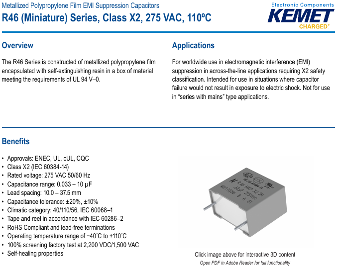 Interesting, right ? The capacitor is X2 SH, ok to connect across the line, but not ok to connect across the line with some LED in series. They don't say why. My guess is, that this capacitor requires some minimum short circuit current in order to blow off damaged plate areas cleanly, which is not guaranteed in a "ballast" application If this guess is correct, then what could happen when this capacitor is in series with some 22 Ohm resistor, and it fails ? The short circtuit current would be (for 230V) up to 10A. This is not sufficient to trip any breakers, it might be too low for the capacitor SH function too. Your last line of defense was the resistor.. except that you used one of a non fusible type Do consider such cases when you choose the components (for something that's going for use outside of the testbench environment) One of the specifics of fusible resistors is, that (the proper ones) don't arc across when they blow. If the resistor arcs across, then it's resistance is not useful to limit the current... The main rules for sizing the resistor are : - Sufficient resistance, to stay within the peak current withstand capability of the device to be ballasted, atleast under worst case condition (unplugged and plugged back in after half cycle). Consider that there may be a few successive peaks in a fast sequence, such as when a bad connection in series with the device is arcing - Not any higher resistance, to not dissipate power excessively - Fusible resistor power (external size) according to the expected load current, with some margin to not be on the edge, including at the highest ambient temp you expect - Not too high current rating, so it still will blow in case of catastrophic failure I think HF AC is the most efficient way to drive Fluorescents : - In DC there is Mercury migration. That means, that only in a small area of the tube there is the optimal concentration of Mercury, in the rest of the tube there is too much or too little - In HF AC i'd expect that some of the current is conducted capacitively from the electrode to the discharge. This is good because this current is not subject to the resistive cathode drop - Inductive, capacitive, etc. "losses" - As induction and capacitance are reactive impedances, the current going through them does not carry power, so there is no actual power loss involved Yep, that isn't about speed of moving of the individual electrons. That speed is on the order of millimeter/sec IIRC. The speed of propagation of electrical field in the conductor (what we would normally consider as the speed of electrical current reaching along the conductor) is on the order of the speed of light However, it's close enough to describe the current as "how fast is the charge moving" (in terms of electrons/sec, or in metric units, Coulomb/sec) |
|
|
|
 Logged
|
|
Keyless
Member

Offline
View
Posts
View Gallery
|
It is not meant as a real "speed", but rather a flow. But the "speed" is sometimes quite a convenient word for that, even when it is not technically correct.
Thanks for clearing it up. Flow as in quantity or amount... I tend to take words literally hence the confusion. |
|
|
|
Logged
|
|
Keyless
Member
Offline
View
Posts
View Gallery
|
X and Y caps should not fail shorted, but capacitors really do fail shorted, it's a matter of how they react (and how fast) to the fault to stay within the requirements
Have a look at part from a datasheet :
Interesting, right ?
That would be a bit of an understatement- I never knew that. So what about capacitors in switch mode power supplies that connect the primary and secondary together? https://i.stack.imgur.com/Du7DE.pngThe capacitor is X2 SH, ok to connect across the line, but not ok to connect across the line with some LED in series. They don't say why. My guess is, that this capacitor requires some minimum short circuit current in order to blow off damaged plate areas cleanly, which is not guaranteed in a "ballast" application
From my point of view your guess is correct. Load in series with the cap will limit the current as compared to being directly across the mains. If this guess is correct, then what could happen when this capacitor is in series with some 22 Ohm resistor, and it fails ? The short circtuit current would be (for 230V) up to 10A. This is not sufficient to trip any breakers, it might be too low for the capacitor SH function too. Your last line of defense was the resistor.. except that you used one of a non fusible type
Do consider such cases when you choose the components (for something that's going for use outside of the testbench environment)
One of the specifics of fusible resistors is, that (the proper ones) don't arc across when they blow. If the resistor arcs across, then it's resistance is not useful to limit the current...
My plan is to mitigate this via a line fuse. The resistor will limit the current and heat up only to the point which the fuse blows- time current curve below the resistor "short circuit" current. Because the resistor limits current to a dozen amps, I do not have to worry about exceeding the low interrupting rating of the glass fuse nor do I have to worry about the resistor over heating. At least this is my current plan. The main rules for sizing the resistor are :
- Sufficient resistance, to stay within the peak current withstand capability of the device to be ballasted, at least under worst case condition (unplugged and plugged back in after half cycle). Consider that there may be a few successive peaks in a fast sequence, such as when a bad connection in series with the device is arcing
- Not any higher resistance, to not dissipate power excessively
- Fusible resistor power (external size) according to the expected load current, with some margin to not be on the edge, including at the highest ambient temp you expect
- Not too high current rating, so it still will blow in case of catastrophic failure
I'd imagine a fluorescent tube can take one heck of a wallop- but unsure about LEDs. For worse case I calculate the peak current let through duration for 1/2 to one cycle, as though the cap is shorted and only the resistor is considered in the equation? I plan on ignoring arcing fauls (other than normal switching), in that my understanding is that unless the resistor makes the bulk of the ballasting Z (impedance) the LEDs will fail regardless. Veering of but still somewhat related, does a higher Z (R) resistor relative to capacitor Z (Jx) in the total impedance (Z=R+JX) lower the current crest factor or it remains the same? I think HF AC is the most efficient way to drive Fluorescents :
- In DC there is Mercury migration. That means, that only in a small area of the tube there is the optimal concentration of Mercury, in the rest of the tube there is too much or too little
- In HF AC i'd expect that some of the current is conducted capacitively from the electrode to the discharge. This is good because this current is not subject to the resistive cathode drop
- Inductive, capacitive, etc. "losses" - As induction and capacitance are reactive impedances, the current going through them does not carry power, so there is no actual power loss involved
If you had to choose: you would pick 50/60Hz over DC when driving a CFL or T5? I am only considering this circuit due to the simplicity, however, if the life or lumens take to much of a dip, then I will scratch it off my list. I can live with multi color tube though   Yep, that isn't about speed of moving of the individual electrons. That speed is on the order of millimeter/sec IIRC. The speed of propagation of electrical field in the conductor (what we would normally consider as the speed of electrical current reaching along the conductor) is on the order of the speed of light
However, it's close enough to describe the current as "how fast is the charge moving" (in terms of electrons/sec, or in metric units, Coulomb/sec)
Got it  |
|
|
|
Logged
|
|
Medved
Member
Offline
Gender: 
View
Posts
View Gallery
|
| There is one very important difference between "X" vs "Y" rated capacitors:
The "X" should be fire safe in case they break down (due to any cause), that means e.g. featuring the selfhealing property is good enough.
Of course, the rating is valid only for certain use, so is limited to only certain conditions (e.g. no extra series impedance to mains voltage, presence of an external fuse,...)
The "Y" rated should be made so, no single internal point failure could lead to leakage greater than allowed as a PE (ground) leakage. That means a self-healing feature does not help at all, but an internal construction using multiple, space separated internal capacitors in series does work, provided each of them has dielectric strength corresponding to the overall strength requirements. Plus the construction must be so, the short circuit or elevated leakage failure modes are made very unlikely (thick enough dielectric layer, the material quality control, sufficient spacing from the metalized part towards the edge of the dielectric plate, surface protection and treatment, presence of a nondestructive current bleed when overvoltage above the rated dielectric strength happens,...)
Again, the rating may be conditioned, e.g. by the need for static electricity bleeding resistor, spark gap, need to have multiple in series ()...
The consequence is, you can not make more than few nF of "Y" rating...
So these types can not be interchanged, where an "X" is specified, you should use an "X" type with particular rating, where an "Y" is specified, you can not use "X" and vice versa.
And regarding the fusible resistors: These are rated as fusible only when certain mounting conditions are met, namely no conductive metal in the proximity, need for heat resistant sleeve, robustness of the surrounding against flying yellow hot fragments (all I've seen had this limitation mentioned in their datasheet), etc.
All these you find in the corresponding datasheet and application notes. And when there is no limitations mentioned with some unknown brand, usually it means the component heavily lacks on real quality, as it is practically impossible for the component maker to avoid all of the limitations and still be compliant with the standards...
|
|
|
|
Logged
|
No more selfballasted c***
|
Ash
Member
Offline
View
Posts
View Gallery
|
So what about capacitors in switch mode power supplies that connect the primary and secondary together? Should not fail shorted. This does not change the fact, that i found one with a hole blown through it in a PC power supply that was tripping the RCD. In this case, no dangerous situation happened as the secondary of the power supply is connected to PE. In a SELV power supply this would make the output live at line voltage My plan is to mitigate this via a line fuse. The resistor will limit the current and heat up only to the point which the fuse blows- time current curve below the resistor "short circuit" current. Because the resistor limits current to a dozen amps, I do not have to worry about exceeding the low interrupting rating of the glass fuse nor do I have to worry about the resistor over heating. At least this is my current plan. There is some range of current, which is too close or exceed the fuse rating, but still not high enough to blow the fuse for sure (and in short enough time, before the resistor overheats enough to pose a danger by itself). So there may happen (not necessarily will) a situation, where you choose a fuse rating, lower you can't go because of the normal operation current draw (and deratings for ambient temp, and some headroom to not load the fuse on the edge all the time), yet it allready is too high to protect the resistor. And if you choose higher power resistor (bigger size with bigger thermal mass), it might be too big to fit where you want it And how would the fuse vs. the resistor curves work together if the current is limited by something else ? For example, a non dead short in the capacitor (cause of failed SH event), damaged LEDs that failed into some resistive mode, etc ? I'd imagine a fluorescent tube can take one heck of a wallop- but unsure about LEDs. You might want to avoid this, as it will happen on cold cathodes and sputter them quite badly LEDs have some rating for current spike. If you exceed that, they might start degrading or outright failing For worse case I calculate the peak current let through duration for 1/2 to one cycle, as though the cap is shorted and only the resistor is considered in the equation? I plan on ignoring arcing fauls (other than normal switching), in that my understanding is that unless the resistor makes the bulk of the ballasting Z (impedance) the LEDs will fail regardless. This is too bad even compared to the real world worst case. You calculate the time as if it is half cycle, but for resistor/capacitor values like what's found in such devices normally, the capacitor charges up (and the current spike ends) way faster than that Arcing is not necessarily a result of fault, some "silent" switches, plugging a plug into a receptacle with loose contacts, etc can produce a series of current spikes... In an experiment i done once this could really be seen : Connect a ~25W GLS lamp in series with ~0.5..1uF capacitor and see how the lamp brightens up if you hold the plug in arcing position Veering of but still somewhat related, does a higher Z (R) resistor relative to capacitor Z (Jx) in the total impedance (Z=R+JX) lower the current crest factor or it remains the same? It sure does. Question is, maybe by the point where it really improves significantly, the resistor is so much dominant that you could omit the capacitor altogether... If you had to choose: you would pick 50/60Hz over DC when driving a CFL or T5? I am only considering this circuit due to the simplicity, however, if the life or lumens take to much of a dip, then I will scratch it off my list. I can live with multi color tube though The Mercury migration means that part of the tube that is Mercury starved, lights less efficiently With DC there is also, that one cathode have the losses on it all the time, so to prevent it from overheating (in a lamp designed for AC) you might want to underdrive the lamp. And that might have its own effect on lamp efficacy too (for example by lowering even more the available Mercury vapor quantity), i dont know how significant this effect will be I'd use 50/60 Hz AC and try to provide as good starting as possible (so electronic starter or RS etc). But it's just my guess |
|
|
|
Logged
|
|
Keyless
Member
Offline
View
Posts
View Gallery
|
There is one very important difference between "X" vs "Y" rated capacitors:
The "X" should be fire safe in case they break down (due to any cause), that means e.g. featuring the selfhealing property is good enough.
Of course, the rating is valid only for certain use, so is limited to only certain conditions (e.g. no extra series impedance to mains voltage, presence of an external fuse,...)
The "Y" rated should be made so, no single internal point failure could lead to leakage greater than allowed as a PE (ground) leakage. That means a self-healing feature does not help at all, but an internal construction using multiple, space separated internal capacitors in series does work, provided each of them has dielectric strength corresponding to the overall strength requirements. Plus the construction must be so, the short circuit or elevated leakage failure modes are made very unlikely (thick enough dielectric layer, the material quality control, sufficient spacing from the metalized part towards the edge of the dielectric plate, surface protection and treatment, presence of a nondestructive current bleed when overvoltage above the rated dielectric strength happens,...)
Again, the rating may be conditioned, e.g. by the need for static electricity bleeding resistor, spark gap, need to have multiple in series ()...
The consequence is, you can not make more than few nF of "Y" rating...
So these types can not be interchanged, where an "X" is specified, you should use an "X" type with particular rating, where an "Y" is specified, you can not use "X" and vice versa. Cleared up a bit of confusion between the two. And would explain why I could not find a Y rated several mico-farads. Personally my go to cap for anything AC is this: https://www.google.com/search?biw=1440&bih=725&tbm=isch&sa=1&ei=0H3tWoD2D4XCzwKMjpcY&q=metalized+film+capcirotr&oq=metalized+film+capcirotr&gs_l=img.3...45806.54546.0.55078.23.22.1.0.0.0.76.1404.22.22.0....0...1c.1.64.img..0.0.0....0.LMGNg9u87GU#imgrc=L8QYXNNcqTRM8M: Not sure where these stand, but its what I use and feel most comfortable working with. Plus I like the way they look on circuit boards- they stand out. I know, my visual appreciation goes well beyond lighting. And regarding the fusible resistors: These are rated as fusible only when certain mounting conditions are met, namely no conductive metal in the proximity, need for heat resistant sleeve, robustness of the surrounding against flying yellow hot fragments (all I've seen had this limitation mentioned in their datasheet), etc.
All these you find in the corresponding datasheet and application notes. And when there is no limitations mentioned with some unknown brand, usually it means the component heavily lacks on real quality, as it is practically impossible for the component maker to avoid all of the limitations and still be compliant with the standards... Good to know- and why I plan on using a fuse. But to be honest, most of the dropper flouro ballasts that I have seen use neither a fuse or flame proof resistor as in this for example: https://www.google.com/search?q=fluorescent+night+light&source=lnms&tbm=isch&sa=X&ved=2ahUKEwje59yopu7aAhVB0lMKHaC1DgcQ_AUoAnoECAAQBA&biw=1440&bih=725#imgrc=fkzRh8zDLLtOsM: If the cap shorts Id think that resistor would get very hot? Or they have a way around that? |
|
|
|
Logged
|
|
Keyless
Member
Offline
View
Posts
View Gallery
|
Should not fail shorted. This does not change the fact, that i found one with a hole blown through it in a PC power supply that was tripping the RCD. In this case, no dangerous situation happened as the secondary of the power supply is connected to PE. In a SELV power supply this would make the output live at line voltage
There is some range of current, which is too close or exceed the fuse rating, but still not high enough to blow the fuse for sure (and in short enough time, before the resistor overheats enough to pose a danger by itself). So there may happen (not necessarily will) a situation, where you choose a fuse rating, lower you can't go because of the normal operation current draw (and deratings for ambient temp, and some headroom to not load the fuse on the edge all the time), yet it allready is too high to protect the resistor. And if you choose higher power resistor (bigger size with bigger thermal mass), it might be too big to fit where you want it
And how would the fuse vs. the resistor curves work together if the current is limited by something else ? For example, a non dead short in the capacitor (cause of failed SH event), damaged LEDs that failed into some resistive mode, etc ?
You might want to avoid this, as it will happen on cold cathodes and sputter them quite badly
LEDs have some rating for current spike. If you exceed that, they might start degrading or outright failing
This is too bad even compared to the real world worst case. You calculate the time as if it is half cycle, but for resistor/capacitor values like what's found in such devices normally, the capacitor charges up (and the current spike ends) way faster than that
Arcing is not necessarily a result of fault, some "silent" switches, plugging a plug into a receptacle with loose contacts, etc can produce a series of current spikes... In an experiment i done once this could really be seen : Connect a ~25W GLS lamp in series with ~0.5..1uF capacitor and see how the lamp brightens up if you hold the plug in arcing position
Well, can't add much other than I agree with your thinking. If wondering the compartment I have to work with is the size of a typical CFL (think Sylvania straight tube or Philips Marathon) at worst so room is generous. It sure does. Question is, maybe by the point where it really improves significantly, the resistor is so much dominant that you could omit the capacitor altogether... I will when designing a high power factor dropper for LED... In theory one could make such a beast for commercial applications- it would meet PF requirements and still use less power than two F40T12s with magnetic ballast. Troffer would dissipate the heat. Then again maybe to much heat for that type of lumen output. The Mercury migration means that part of the tube that is Mercury starved, lights less efficiently
With DC there is also, that one cathode have the losses on it all the time, so to prevent it from overheating (in a lamp designed for AC) you might want to underdrive the lamp. And that might have its own effect on lamp efficacy too (for example by lowering even more the available Mercury vapor quantity), i dont know how significant this effect will be
I'd use 50/60 Hz AC and try to provide as good starting as possible (so electronic starter or RS etc). But it's just my guess
An educated guess- AC it is then. I found this data which has me addled on one (actually two) thing: https://products.currentbyge.com/sites/products.currentbyge.com/files/documents/document_file/20504_GE_CFL_Biax_T_E_SellSheet.pdfOn the last page under starting requirements, you have "Minimum OCV at +10*C" and then "Maximum OCV (none-ignition)" What do they mean by this...? IS this a cold cathode value? Or once the electrodes have heated up? And what is Rsub (ohm)? |
|
|
« Last Edit: May 05, 2018, 06:20:19 AM by Keyless »
|
Logged
|
|
Ash
Member
Offline
View
Posts
View Gallery
|
Well, can't add much other than I agree with your thinking. If wondering the compartment I have to work with is the size of a typical CFL (think Sylvania straight tube or Philips Marathon) at worst so room is generous All that was related to what if a standard (not fusible) resistor is used. With enough space this might be possible If you do use a fusible resistor (and choose it and use it correctly), then the range in which you must ensure safety without blowing is shorter, as above that the resistor will fuse as it's meant to. The benefit is that, the overheating of the resistor is what brings it towards fusing, there are no 2 components that have to be matched under all conditions I will when designing a high power factor dropper for LED... In theory one could make such a beast for commercial applications- it would meet PF requirements and still use less power than two F40T12s with magnetic ballast. Troffer would dissipate the heat. Then again maybe to much heat for that type of lumen output. The requirement for high power factor came from desire to eliminate the reactive current on the supply. That is, draw only as little current as really required to get things working Lets say you power a LED or a series string of few of them at 10mA, using a simple series ballast. The current draw from the line will be 10mA no matter whether your ballast is a capacitor, a resistor, or any combination of them. So you don't improve anything on that side by using resistor However, with the capacitor the extra power (capacitor Vdrop * 10mA) is entirely reactive and carries no real power, but with the resistor (resistor Vdrop * 10mA) it's all real power losses going to heat So : Resistor is useful where the current draw is tiny and even a capacitor is overkill, Such as in indicators, illuminated switches and such. And is pretty much the most reliable option Capacitor is usefull where the current draw is small (few LEDs, or some minimal control device, etc) and the simplest way to supply it with power is required Switching power supply covers most applications the most efficiently 50Hz stepdown transformer + linear regulator or similar, is better than the resistor on efficiency (the linear regulator is as efficient as resistor, but with a stepdown transformer there is less voltage to drop on it), better than the capacitor on current draw, and better than switching power supply on reliability For higher currents - of 100mA and up - a series inductor becomes an option too, the concept is similar to the capacitor but with few advantages : - Excellent crest factor (good for discharge lamps) - Low pass behavior - Spikes in the supply voltage are blocked, instead of being highly conducted - High reliability - Can be PFC'd by using a capacitor as PFC - Can be used as a means for starting a lamp in addition to the ballast function And here come all the magnetic ballasts for FL and HID lamps I found this data which has me addled on one (actually two) thing:
https://products.currentbyge.com/sites/products.currentbyge.com/files/documents/document_file/20504_GE_CFL_Biax_T_E_SellSheet.pdf
On the last page under starting requirements, you have "Minimum OCV at +10*C" and then "Maximum OCV (none-ignition)" What do they mean by this...? IS this a cold cathode value? Or once the electrodes have heated up? And what is Rsub (ohm)? Max Voc with which they guarantee the lamp won't start. It's RMS value, so the actual peak voltage would be sqrt(2) times that But there are some factors that could have effect here : Temperature of the cathodes as you pointed out, temp of the lamp as whole (would this still hold at the max rated temp for the lamp ?), Presence of ionizing radiation (could the lamp strike if a particle enters it - so with some chance anytime anywhere), Presence of residual vapors in the lamp (minimum time from lamp switch off), and maybe something else The resistor i guess is what you connect to the ballast output to substitute for the lamp cathodes, to enable the ballast to start. The resistor will be subjected to few Watts (cathode heating power) when the ballast tries to power up What i would do is, connect 2 lamps to the ballast, so it preheats one cathode in each lamp but cannot start a discharge |
|
|
|
Logged
|
|
Keyless
Member
Offline
View
Posts
View Gallery
|
|
|
|
|
Logged
|
|
Ash
Member
Offline
View
Posts
View Gallery
|
| Inductor acts as impedance for AC. So yep, it could. It's mainly not done because it's cheaper to use capacitor for the low currents used mostly with low power LEDs (so pretty much anything that uses 5mm LEDs)
When current through inductor is interrupted, it generates voltage such, to try to maintain the same current. With loads that dont conduct below a minimal voltage : Discharge lamps, strings of LEDs, anything that rectifies the line voltage with a with full bridge rectifier and capacitor without PFC, etc. When the line voltage drops below the minimum voltage, the current stops. If there is inductor added in series, the current will continue for longer and the stops will become shorter, so the crest factor gets improved
One application is in PC power supplies. There are power supplies with boost-converter PFC (active PFC) - a boost converter between the bridge rectifier and the big electrolitic capacitor (that can be seen as a constant voltage component). And there are power supplies with no PFC, that draw a spike of current only near the peak of the input sine wave (so, high crest factor and low power factor on the order of 1/2). In the latter, adding an inductor in series with the AC input, without changing anything else in the PS design, improves both very considerably - The power factor can improve to as high as 3/4, and allready pass EU regulation. The addition of inductor have been done in many PS's and got called Passive PFC for it's PFC feature
A proper resonant circuit won't ballast the lamp... The designs of ballasts like SRS or like frequency-sweep start (as in CFLs) are much about getting a not really resonant circuit to do what we want and not what a resonant circuit from the schoolbook does. This is engineering in the whole meaning of it...
|
|
|
|
Logged
|
|
Keyless
Member
Offline
View
Posts
View Gallery
|
Inductor acts as impedance for AC. So yep, it could. It's mainly not done because it's cheaper to use capacitor for the low currents used mostly with low power LEDs (so pretty much anything that uses 5mm LEDs)
When current through inductor is interrupted, it generates voltage such, to try to maintain the same current. With loads that dont conduct below a minimal voltage : Discharge lamps, strings of LEDs, anything that rectifies the line voltage with a with full bridge rectifier and capacitor without PFC, etc. When the line voltage drops below the minimum voltage, the current stops. If there is inductor added in series, the current will continue for longer and the stops will become shorter, so the crest factor gets improved But these spikes will not kill the LED string, correct? At least not under normal conditions. I could see an intermittent failing LED creating some huge voltage spikes much like a glow starter dropping out and striking a tube. One application is in PC power supplies. There are power supplies with boost-converter PFC (active PFC) - a boost converter between the bridge rectifier and the big electrolitic capacitor (that can be seen as a constant voltage component). And there are power supplies with no PFC, that draw a spike of current only near the peak of the input sine wave (so, high crest factor and low power factor on the order of 1/2). In the latter, adding an inductor in series with the AC input, without changing anything else in the PS design, improves both very considerably - The power factor can improve to as high as 3/4, and allready pass EU regulation. The addition of inductor have been done in many PS's and got called Passive PFC for it's PFC feature
I will Google these terms and do my research if I ever get bored and want to do a high power LED ballast. Even if I don't, its worth knowing. Its kind of funny though, even though we have moved into a semiconductor world and LEDs, I am thinking about how to drive them with magnetic ballasts. That would kind of be neat, a cobra head with a magnetic driver and the open board igniter being a bridge rectifier. A proper resonant circuit won't ballast the lamp... The designs of ballasts like SRS or like frequency-sweep start (as in CFLs) are much about getting a not really resonant circuit to do what we want and not what a resonant circuit from the schoolbook does. This is engineering in the whole meaning of it... A true resonant circuit- but there is a key to the madness- or at least not having it. I have seen 120 volt US shop with a series capacitor and inductor driving the T12 40 watt tubes. Had a Sidac starter... A few members will instantly know what I am referring to. |
|
|
|
Logged
|
|
Ash
Member
Offline
View
Posts
View Gallery
|
But these spikes will not kill the LED string, correct? At least not under normal conditions. I could see an intermittent failing LED creating some huge voltage spikes much like a glow starter dropping out and striking a tube. It's a matter of the size of the spikes and the withstand capability of the LEDs... - The size of the spikes can be estimated as long as you can describe (to yourself) what happened that generated them. Such single plugging-unplugging, arcing connection, line voltage transient (of what voltage and duration ?), and so on - The withstand capability of the LEDs gotta be stated in the datasheet Voltage-wise, the bad connection in series with capacitor and the glow starter do very different things : The capacitor can, at most, make double the peak line voltage appear on any open circuit area in series with it. (peak line voltage coming from the line + peak line voltage charged in the capacitor from previous time) The inductor ballast, generates voltage which is equal to L di/dt. In theory, if the circuit is abruptly opened then dt=0 and so the voltage would be infinite. In reality, capacitances between conductors make dt non-zero, arcing across opening contacts limits the voltage, and so on. So you get something on the order of 1..1.5kV out of a Preheat ballast. This have little to do with the line voltage - you could get similar voltage spikes from a Fluorescent ballast even when powering it with a 9V battery I will Google these terms and do my research if I ever get bored and want to do a high power LED ballast. Even if I don't, its worth knowing. Its kind of funny though, even though we have moved into a semiconductor world and LEDs, I am thinking about how to drive them with magnetic ballasts. That would kind of be neat, a cobra head with a magnetic driver and the open board igniter being a bridge rectifier. Why go that far. Most emergency lighting (atleast here) is powered in standby with plain simple transformer working at 50 or 60Hz. The load on this transformer is float charging of the (fairly small) battery + lighting up an indicator LED I do know of an attempt to commercialize magnetic LED drivers at one of our local lighting manufacturers a few years ago. They were quite powerful, 60W in about the same size as a 58W Fluorescent lamp ballast. There were a few batches made but it never took up and ended up being dismissed A true resonant circuit- but there is a key to the madness- or at least not having it. I have seen 120 volt US shop with a series capacitor and inductor driving the T12 40 watt tubes. Had a Sidac starter... A few members will instantly know what I am referring to. Any L+C circuit is a resonant circuit for some frequency, but L+C circuits used for lamp ballasting are not resonating at 50/60Hz (if they would, the ballast would not perform any ballasting) The capacitor and inductor are 2 storage components (the inductor can store current, in much the same way as a capacitor stores voltage). If connected together and some initial energy provided, this energy will travel between them forward and back forever (subject to losses). If external energy is supplied at the same timings, as the energy allready present in the storage moves, then it will add up. (Swinging yourself on a swing set) The impedance of L is : XL = 2pi f L The impedance of C is : XC = 1 / ( 2pi f C ) At some frequency, XL = XC exactly (and the phase is opposite). That means, that if they are connected in a closed loop, the voltage and current of one of them match the voltage and current of the other all the time, so each one can exactly discharge into the other, enabling the infinite energy travel of resonance forward and back In the lamp ballast you mentioned, at 60Hz XC is bigger than XL (by 2 times or more). The overall impedance that ballasts the lamp is XC-XL. The inductor is there to provide the starting and to improve the crest factor to be atleast to some extent acceptable |
|
|
|
Logged
|
|
Keyless
Member
Offline
View
Posts
View Gallery
|
Voltage-wise, the bad connection in series with capacitor and the glow starter do very different things :
The capacitor can, at most, make double the peak line voltage appear on any open circuit area in series with it. (peak line voltage coming from the line + peak line voltage charged in the capacitor from previous time)
The inductor ballast, generates voltage which is equal to L di/dt. In theory, if the circuit is abruptly opened then dt=0 and so the voltage would be infinite. In reality, capacitances between conductors make dt non-zero, arcing across opening contacts limits the voltage, and so on. So you get something on the order of 1..1.5kV out of a Preheat ballast. This have little to do with the line voltage - you could get similar voltage spikes from a Fluorescent ballast even when powering it with a 9V battery
Well, I guess you could say I have learned what I already knew but really did not if that makes sense... An inductor generates voltage based on the collapsing field- the rate of current change- and not dependent on the input voltage.
So if lets say a LED goes instantly open, the inductor could in theory slam a kilovolt or more of voltage across the array?
Why go that far. Most emergency lighting (atleast here) is powered in standby with plain simple transformer working at 50 or 60Hz. The load on this transformer is float charging of the (fairly small) battery + lighting up an indicator LED
In other words ballasting a LED through a very high impedance transformer? I've seen NEON signs where the ballast was literally nothing more than a 2 winding transformer. Bascially a transformer that could operate with the secondary short circuited for some time. Then you have CWI ballasts... However I have no idea how to design one.
I do know of an attempt to commercialize magnetic LED drivers at one of our local lighting manufacturers a few years ago. They were quite powerful, 60W in about the same size as a 58W Fluorescent lamp ballast. There were a few batches made but it never took up and ended up being dismissed
Do you have any more info or knowledge about this or their design?
Do you have more info on this?
Any L+C circuit is a resonant circuit for some frequency, but L+C circuits used for lamp ballasting are not resonating at 50/60Hz (if they would, the ballast would not perform any ballasting)
The capacitor and inductor are 2 storage components (the inductor can store current, in much the same way as a capacitor stores voltage). If connected together and some initial energy provided, this energy will travel between them forward and back forever (subject to losses). If external energy is supplied at the same timings, as the energy allready present in the storage moves, then it will add up. (Swinging yourself on a swing set)
The impedance of L is :
XL = 2pi f L
The impedance of C is :
XC = 1 / ( 2pi f C )
At some frequency, XL = XC exactly (and the phase is opposite). That means, that if they are connected in a closed loop, the voltage and current of one of them match the voltage and current of the other all the time, so each one can exactly discharge into the other, enabling the infinite energy travel of resonance forward and back
In the lamp ballast you mentioned, at 60Hz XC is bigger than XL (by 2 times or more). The overall impedance that ballasts the lamp is XC-XL. The inductor is there to provide the starting and to improve the crest factor to be atleast to some extent acceptable
By any chance does this (the shop light) circuit increase the voltage? What always mystified me is that American 40 watt T12s require a 240 volt source (reactor) or a 120 volt ballast with a voltage step up scheme (HX). Yet the shoplight appears to drive these without that at first glance.
|
|
|
|
Logged
|
|
Ash
Member
Offline
View
Posts
View Gallery
|
Well, I guess you could say I have learned what I already knew but really did not if that makes sense... An inductor generates voltage based on the collapsing field- the rate of current change- and not dependent on the input voltage.
So if lets say a LED goes instantly open, the inductor could in theory slam a kilovolt or more of voltage across the array? Have you noticed how inductor and capacitor are mirror of each other ? Ic = C dV/dt Vl = L dI/dt (for sine wave AC : ) Xc = 1/ ( 2 pi f C ) Xl = 2 pi f C Q (electric charge) = CV ϕ (magnetic flux) = LI Energy stored in capacitor = 1/2 C V^2 Energy stored in inductor = 1/2 L I^2 The inductor will put out an impulse of high voltage, at a current equal to what was flowing through it, at the same direction of current through the inductor. This will light normally the good LEDs for the split second the impulse lasts, and most likely arc across the bad one If the LEDs are a set of multiple parallel arrays or so (so, the one opened LED did not open the circuit completely), then it does not take any high voltage to push the same current (so keeping the current unchanged, dI = 0) through the remaining good LEDs, it'll be only a few V difference across the entire array and that is as much voltage spike as the inductor will give in this case A mirror of your example could happen if we mirror everything : - Capacitor instead of inductor - Parallel LED array instead of series - One LED shorted instead of open - Power source is constant current source instead of constant voltage (still AC. You could imagine this as taking place on the output of a LED driver) When the LED fails shorted, there is abrupt voltage change from ~3V (the LED Vforward) to 0V (the short). dV/dt --> infinity and so this causes a high current spike from the capacitor. The spike will obviously go into the shorted LED, blowing it open if there is enough current/energy In other words ballasting a LED through a very high impedance transformer? I've seen NEON signs where the ballast was literally nothing more than a 2 winding transformer. Bascially a transformer that could operate with the secondary short circuited for some time. Then you have CWI ballasts... However I have no idea how to design one.
Do you have any more info or knowledge about this or their design?
Do you have more info on this? The devices were made in a transformer format which is not capable of adding shunts, so it could not be anything like HX, CWI or so. I think it was plain stepdown transformer with integrated bridge rectifier, feeding some "12V DC" LED devices with their own ballasting inside This would improve reliability by standing between the line and the LED modules with their electronics, as such transformers don't pass through spikes as well as direct connection to line-voltage electronics By any chance does this (the shop light) circuit increase the voltage? What always mystified me is that American 40 watt T12s require a 240 volt source (reactor) or a 120 volt ballast with a voltage step up scheme (HX). Yet the shoplight appears to drive these without that at first glance. LC circuits can step up voltage. Example of how this. Think of series LC connected to AC source : Vin = 1 V Xl = 1000 Ohm Xc = 900 Ohm X = Xl - Xc = 1000 - 900 = 100 Ohm I = Vin / X = 1V / 100 Ohm = 10 mA Vl = I Xl = 10 mA * 1000 Ohm = 10 V Vc = I Xc = 10 mA * 900 Ohm = 9 V Yep, between the ends is the input 1V, but across each component alone the voltage is much higher, according to the choice of L and C values In the shoplight, if i imagine it's internals correctly, the lamp is not connected to the mid point between the L C so this does not take place. The story is just how to drop voltage on the ballast without taking up too much voltage headroom from the lamp. Since the voltage drop on the lamp and on the ballast (mostly capacitive) are near 90deg out of phase, there is room to drop several 10's V on the capacitor (well, the inductor + capacitor together), even when the voltage of the lamp is close to that of the line But managing 103V lamp reliably (enough so it works most of the time !) on a voltage source that could go as low as 110V still surprises me. I tried dimming a 36W T8 (with plain choke ballast, which is few 100's Ohm inductive + 45 Ohm or so resistive) on a variac - At 160V variac output or so it will go out right away |
|
|
|
Logged
|
|
Keyless
Member
Offline
View
Posts
View Gallery
|
LC circuits can step up voltage. Example of how this. Think of series LC connected to AC source :
Vin = 1 V
Xl = 1000 Ohm
Xc = 900 Ohm
X = Xl - Xc = 1000 - 900 = 100 Ohm
I = Vin / X = 1V / 100 Ohm = 10 mA
Vl = I Xl = 10 mA * 1000 Ohm = 10 V
Vc = I Xc = 10 mA * 900 Ohm = 9 V
Yep, between the ends is the input 1V, but across each component alone the voltage is much higher, according to the choice of L and C values That solves the mystery! Truly shows you can do anything with math- from manipulating physics to changing the anatomical structure of the universe. In the shoplight, if i imagine it's internals correctly, the lamp is not connected to the mid point between the L C so this does not take place. The story is just how to drop voltage on the ballast without taking up too much voltage headroom from the lamp. Since the voltage drop on the lamp and on the ballast (mostly capacitive) are near 90deg out of phase, there is room to drop several 10's V on the capacitor (well, the inductor + capacitor together), even when the voltage of the lamp is close to that of the line The one I had went like this: Live in- Big red metalized film capacitor with resistor across it- Inductor (about the size of a 8-13 watt preheat if that and windings that were so thin I remember saying to myself what the...)- tube tommbestone- electronic starter consisting of a sidac, diode and a a few resitors- tube tombstone- neutral. Here is what I am talking about: http://www.sozialize.me/48784/convert-fluorescent-light-to-led/mesmerizing-convert-fluorescent-light-to-led-19-convert-fluorescent-shop-light-to-led-fluorescent-shoplights-ballasts/https://www.lighting-gallery.net/gallery/displayimage.php?album=657&pos=158&pid=79249The starter: https://www.lighting-gallery.net/gallery/displayimage.php?album=307&pos=0&pid=79291At 0:47 and on the overall light and design: https://www.youtube.com/watch?v=kcyaQ3ThU5c But managing 103V lamp reliably (enough so it works most of the time !) on a voltage source that could go as low as 110V still surprises me. I tried dimming a 36W T8 (with plain choke ballast, which is few 100's Ohm inductive + 45 Ohm or so resistive) on a variac - At 160V variac output or so it will go out right away If it surprises you, imagine what its doing to me LOL. When I first saw it I didn't understand how it was possible- then I assumed that 40 watt tubes actually ran at 60 volts operating- only to then not figure out why I couldn't get 40 watt tubes to light on a 120 volt source... Also I could not understand how the inductor didn't overheat or burn up. Eventually I assumed it is what it is and forgot about it. At the time it really want on my to do or interest list. FWIW, these shop lights do not like watt misser or 34 watt T12s and 32 watt T8 watt. They would just buzz and flickr. I think my links make mention of that, I remember scoring a huge supply of 32 watt tubes for my workshop and trying them out in the shop lights I had. I was so made they didn't work out. Eventually I scored some T8 high bays. Absolutely the best work lighting I ever had. |
|
|
|
Logged
|
|