HomeBrewLamps
Member

Offline
Gender: 
View
Posts
View Gallery

    
|
I was hoping to get a homework check to make sure I am not making any mistakes in my PCB design here. I deleted R1 as I intend to dump full battery current through the LED. I am modifying a cheap emergency road beacon "cone light" to have a brighter 3 watt red LED instead of the cheap straw hat LEDs that were in it. I intend on using a Lithium Ion 14400 battery instead of a alkaline 1.5V battery. considering the use case I don't think circuit reliability will be affected too much. even if the LED is over driven or the circuit itself is over volted a little but I am open to any critiques here if you guys think differently... I will post screenshots aswell as the Express PCB version 7.9 file. here is the circuit I am following to make my PCB: lm3909 oscillatorI am aware I could compact it down further with SMD components. I don't have steady enough hands to solder those manually. maybe there might be further ways to compact the current through hole board down? currently it is TO-92 transistors and 0.25 watt resistors... |
|
|
« Last Edit: November 06, 2025, 08:57:53 AM by HomeBrewLamps »
|
 Logged
|

|
Ash
Member
Offline
View
Posts
View Gallery

|
| With supply voltage over 1.5V you can use LMC555, and over 3V you can use ICM7555, both 555 timers using the standard 555 circuit
With supply voltage higher than the LED forward voltage you don't need a charge pump either (that could be implemented whether with the LM3909 or any of the 555)
The 555 circuit requires only the 555 itself (DIP 8 pin), 1 capacitor and 1 resistor (excluding the LED's resistor and any capacitors across the input power) to flash a LED
|
|
|
|
Logged
|
|
RRK
Member
Offline
Gender:
View
Posts
View Gallery
Roman
|
| Main problem is 2N3904 is a bit weak to drive 3W LED. It is only 200mA though you may choose to run the LED at a fraction of maximal power. If you use 3V lithium source, you don't need all the complications of this circuit, and probably can get away with just a simple two-transistor asymmetrical multivibrator (PNP+NPN) or something much more modern as an oscillator of your choice (LMC555? or 74LVC1G14) driving a low-threshold power MOSFET.
|
|
|
|
Logged
|
|
RRK
Member
Offline
Gender:
View
Posts
View Gallery
Roman
|
Some quick ideas from internet search...  Note you actually don't need voltage doubler circuits shown here to run red LED from a Li cell (until it is 3V phosphor converted type!) but a large storage capacitor across the battery may be a good idea. |
|
|
« Last Edit: November 06, 2025, 04:14:51 PM by RRK »
|
Logged
|
|
Medved
Member
Offline
Gender:
View
Posts
View Gallery
|
I assume the idea is tor drive a red LED from a single dry cell battery (alkaline,...), therefore the charge pump arrangement. And that means the circuit needs to work down to about 1V, so things like LMC555 are out of question. Otherwise the battery would have very pathetic life/capacity (see a typical LR6 datasheet). I would just add two resistors into emitters of Q2A/Q2B current mirror, the discrete transistors tend to have way worse mismatch (about 20mV in Vbe so about 2x in current) than what is common on a single chip (2mV in Vbe so about 10% on Ic current), good starting point is to have there about 100mV, so about 10..15 Ohm there The whole circuit could easily be beefed up: Q3 could be some higher power transistor, like SS8050 (1A switch) or so and make the resistor on the Q2B emitter smaller, so the mirror will be increasing the current to get good drive for the Q3 (like 15 Ohm for Q2A, 4.7Ohm for Q2B). Looking at your layout: I see you have reduced the Q2A/B current mirror into just a single transistor. I'm afraid that won't work, the current gain would be way too much there, it needs to be in really low single digits maximum. It is not only about switching the base current, the whole circuit needs to be a reasonable amplifier with sufficient small signal gain around the DC equilibrium point. Due to the feedback via the capacitor it won't be there once started, but such operating point should exist for the circuit to start reliably. So it should have gain more than unity to oscillate with the feedback capacitor, but also not too high so some of the stages would get stuck and so lose all their gain there. |
|
|
« Last Edit: November 07, 2025, 02:09:35 AM by Medved »
|
Logged
|
No more selfballasted c***
|
Ash
Member
Offline
View
Posts
View Gallery
|
| He mentioned using a Lithium battery, so have sufficient voltage headroom to power CMOS ICs and drive LEDs without a charge pump
Small (and still fairly good output) "high efficiency Red" LEDs up to 100mA can be driven directly from the 555, anyhing above that just use an additional MOSFET. (A charge pump for driving larger MOSFETs from the 555 can be implemented with an additional 1 capacitor, 1 resistor and diode)
|
|
|
|
Logged
|
|
RRK
Member
Offline
Gender:
View
Posts
View Gallery
Roman
|
| No, common CMOS 555's won't drive 100mA LED directly at 3V supply. Not near. Read the datasheet...
|
|
|
« Last Edit: November 07, 2025, 04:34:02 AM by RRK »
|
Logged
|
|
Medved
Member
Offline
Gender:
View
Posts
View Gallery
|
... I intend on using a Lithium Ion 14400 battery instead of a alkaline 1.5V battery.
Before I overlooked this remark, but it changes a lot. It means the LM3909 topology won't work at all, it requires the cell voltage to be really lower than the LED. |
|
|
|
Logged
|
No more selfballasted c***
|
Ash
Member
Offline
View
Posts
View Gallery
|
| Right. Then indeed, an external MOSFET
Without a charge pump, suitable MOSFETs may be VN1206 or VN2406 for small loads (100mA range), IRLU024N may be able to drive that 3W LED you mentioned, and many bipolar transistors may work too (but have non-zero current draw for driving)
With a charge pump most common MOSFETs will work
|
|
|
|
Logged
|
|
Medved
Member
Offline
Gender:
View
Posts
View Gallery
|
I would go for bipolars, they are easier to configure into the flasher circuit. The base drive should be no problem with reasonably designed flasher - it flows only when the LED is ON and it needs to be about 4% of the LED current, so not significant. But be aware about the seemingly very simple (two transistor,...) flasher circuits found around the internet: Many rely on circuit parasitics (like battery internal resistance so won't work with modern low impedance batteries, Germanium transistors saturating rather softly so do not work that well with silicon, on a cold incandescent having way lower resistance, many to really low transistor current gain,...), many need explicite kickup, so at the end very often they tend to stay in a kind of "limbo" where the light is permanently ON or OFF and do not oscillate. A good mental test is, what would be the hypothetical operating point of the transistors when you remove all the capacitive feedbacks. If the thing may stay or stays with some transistors fully ON or OFF. 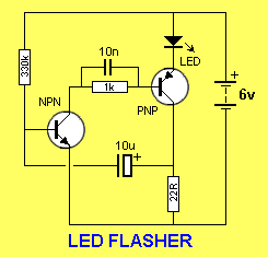 or 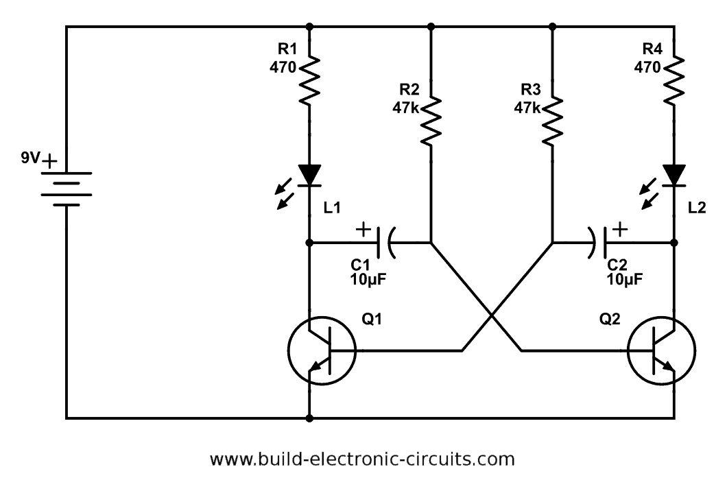 ), the thing won't work in a reliable way. That equilibrium point needs to be with the circuit "somewhere in the middle" - transistors only partially conducting, neither fully ON, nor OFF. From that state the adding of the capacitors will make it unstable so oscillate. Good example is 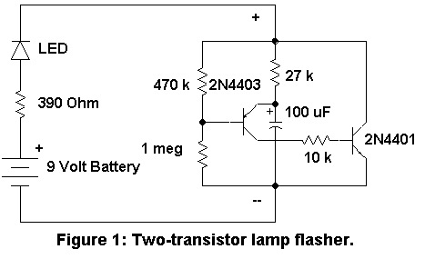 The output transistor just can not stay ON, because it would loose base drive... So without the capacitor the circuit stays in a state where the voltage drop across the output transistor is about 1V or so, so perfectly in the range where it is a good amplifier and not stuck ON switch... My only remark for operation at lower Vbat is you need to add some 100Ohm parallel to the LED (for your case, where the series resistor with LED will be around 1 Ohm or nothing, the base resistor of the power transistor about 100Ohm,...), so full battery voltage will become present across the circuit when the transistor is OFF... |
|
|
« Last Edit: November 07, 2025, 07:14:56 AM by Medved »
|
Logged
|
No more selfballasted c***
|
RRK
Member
Offline
Gender:
View
Posts
View Gallery
Roman
|
These transistors are too impractical as Rds is too high, or threshold voltage is not low enough. AO3400 is a good candidate, it is time tested, even cheap Chinese clones work OK. SI2302, one or a couple in parallel look good too. SOT-23, but what? It is year 2025, no one does through-hole anymore. Learn how to solder SOT-23, it is very easy, we are not talking 0.4mm pitch TSSOP |
|
|
|
Logged
|
|
HomeBrewLamps
Member
Offline
Gender:
View
Posts
View Gallery
|
@RRK plenty of people do through hole. I don't have steady hands and don't have the patience to deal with little dust grains blowing off my table due to someone opening a door or something. or accidentally brushing them off the table with pen or a piece of paper on accident. If you want to raise the skill bar so high that you scare kids away from electronics. then sure, I suppose force them to learn SMD soldering first instead of teaching both and easing into the SMD. I tried SMD and just destroyed/lost components with my caffeine hands and I don't have a re flow oven. I don't see a purpose in subjecting myself to all that when through hole is readily available, easy, cheap, and compact enough that I could work it into the design still. even TO-92 I could make fit. (it is a barrier light type thing). I would not be opposed to someday getting an oven and a bunch of flux, setting components up with tweezers and letting the oven do the work... but today and for the near future I am armed with a hand soldering iron that also happens to have the wrong tip for surface mount stuff. @Ash I will definitely look into doing the standard bipolar route. I really liked the idea of the LM3909 and NTE876 due to their simple DIP8 package. it is quite disappointing to me that they are discontinued. But admittedly I indof tunnel visioned onto that one circuit without thinking about simpler designs. the two transistor flasher is definitely quite a bit simpler. @Medved Theoretically I could just run two LEDs in series to make that circuit work on 3.7V with beefier components yes? I just ask out of curiosity. I don't think I will pursue the LM3909 topology for this particular project.
|
|
|
« Last Edit: November 07, 2025, 08:20:08 AM by HomeBrewLamps »
|
Logged
|
|
RRK
Member
Offline
Gender:
View
Posts
View Gallery
Roman
|
A reality of today is many interesting components are available in SMD only. Why stick with 60 years old 2N3904s when you have nice modern AO3400 MOSFETs switching 5A at 30V with zero current at the gate and minor dissipated power? Soldering SOT23 (and 0805 -1206 passives) is not that complicated, as actual pin pitch is about the same as plastic through hole TO92 case mentioned. For success, you need a temperature controlled soldering iron set to ~320C, with say, 1.5mm flat screwdriver blade tip, some 0.8mm lead solder, and some gel flux. All very inexpensive. Keep the tip clear with a wet sponge, and keep it completely tinned all the time, this is important. Apply an excess of flux, surface tension will really do the rest for you Some prefer to use a soldering paste, no problem, you put some blobs of paste out of a syringe on the board contacts, apply components and reflow with air source of ~350C, heat gun or electronics air tool. No absolute need for a reflow oven. |
|
|
« Last Edit: November 07, 2025, 09:18:56 AM by RRK »
|
Logged
|
|
RRK
Member
Offline
Gender:
View
Posts
View Gallery
Roman
|
@Medved A symmetrical multivibrator you pictured does not have problems starting even using silicon transistors. In practice, RC constants of base networks will always be slightly asymmetrical, enabling the circuit to start.
|
|
|
|
Logged
|
|
HomeBrewLamps
Member
Offline
Gender:
View
Posts
View Gallery
|
A reality of today is many interesting components are available in SMD only. Why stick with 60 years old 2N3904s when you have nice modern AO3400 MOSFETs switching 5A at 30V with zero current at the gate and minor dissipated power? Soldering SOT23 (and 0805 -1206 passives) is not that complicated, as actual pin pitch is about the same as plastic through hole TO92 case mentioned. For success, you need a temperature controlled soldering iron set to ~320C, with say, 1.5mm flat screwdriver blade tip, some 0.8mm lead solder, and some gel flux. All very inexpensive. Keep the tip clear with a wet sponge, and keep it completely tinned all the time, this is important. Apply an excess of flux, surface tension will really do the rest for you
Some prefer to use a soldering paste, no problem, you put some blobs of paste out of a syringe on the board contacts, apply components and reflow with air source of ~350C, heat gun or electronics air tool. No absolute need for a reflow oven.
While I do not disagree with you on the fact that a lot of newer chips are only available in SMD, And I don't disagree that it is not technically complicated. I just don't wish to use SMD for essentially blinken an LED. especially when I have a LARGE supply of THT components either in bins or on scrap PCBs. I have ZERO SMD components aside from high powered LEDs. ironically the 3 watt LEDs i Soldered are SMD lol. and those are really big and I still shock around like a MF trying to set them up and center them with tweezers. I don't know if I have a vitamine defficiency or what. I would be a terrible TIG welder thats for sure  anyway I have like a billion through hole transistors kicking around. and a bazillion resistors. I have a capacitor shortage but I still have enough to make it blink in some sortof way. Check out this cool looking old forklift battery charger PCB with this weird number selector switch on it, resistor networks, a cool little self contained screen with controller chip integrated and old skool TO-92 transistors with heat sinks on top. one of my many scrap PCBs lol. I do wonder if that socketed chip is a ROM or if it re writable. |
|
|
« Last Edit: November 07, 2025, 10:09:15 AM by HomeBrewLamps »
|
Logged
|
|